This post opens the relational data modeling leg of the course. It builds on The Origins of Databases and points ahead to Relational Normalization and SQL Index Performance so you can see how modeling decisions ripple through normalization and query tuning.
Relational data modeling and the DBMS mandate#
Designing a relational database begins with a clear sense of the business domain and the stewardship responsibilities of a Database Management System (DBMS). The model - entities, attributes, and relationships - mirrors the real world while the DBMS enforces integrity, manages concurrency, and shields content from accidental loss. When you trace the origin story of our tooling in “The Origins of Databases”, you can see how the need to tame growing data volumes drove both modeling discipline and the engines that implement it.
Designing and analyzing a relational database#
A resilient relational database emerges from a disciplined workflow rather than from improvising SQL statements. The steps below keep stakeholders aligned and make each successive translation - from humans to diagrams to code - safer.
Requirements analysis#
Start by documenting what users and applications actually need. Capturing goals, expected workloads, data lifecycles, and compliance obligations lets you define the entities, attributes, and relationships that matter. Validate assumptions with subject-matter experts and record non-functional requirements such as availability, retention, and auditing so they steer subsequent phases.
Conceptual modeling#
Once requirements settle, abstract them into a conceptual schema. Draw an Entity-Relationship (ER) diagram that names key entities, their cardinalities, and distinguishing attributes. For example, an e-commerce solution would show customers, products, and orders plus the links that track “which customer placed which order.” Treat this diagram as the shared mental model for stakeholders before you move to implementation.
Logical modeling#
Translate the conceptual schema into tables, columns, and constraints suited to a relational engine. Decide which attributes become foreign keys, which ones need uniqueness guarantees, and how optional data is handled. At this stage you balance normalization with practical query patterns so you know where indexes and derived tables may be needed later.
Normalization#
Normalize carefully to eliminate redundant records and to keep dependencies on keys explicit. First-normal-form rules ensure each cell holds a single value; second and third forms push groups of related columns into their own tables; Boyce-Codd Normal Form covers edge cases where candidate keys overlap. Good normalization reduces anomalies in inserts, updates, and deletes while keeping storage consistency predictable. This article leans on the Relational Normalization primer for the anomaly examples and normal form walkthroughs that reinforce these principles.
Physical modeling#
With the logical model in place, define the physical implementation: pick the DBMS (PostgreSQL, MySQL, SQLite, etc.), specify column types, plan indexes, and model storage considerations such as partitioning or clustering. Security planning also happens here - identify roles, grant least-privilege access, and document which users may read or modify each table.
Implementation#
Now the logical design becomes SQL. Create tables, define primary and foreign keys, and load seed data. You can capture common patterns in snippets such as:
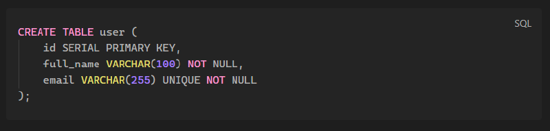
CREATE TABLE users (
user_id SERIAL PRIMARY KEY,
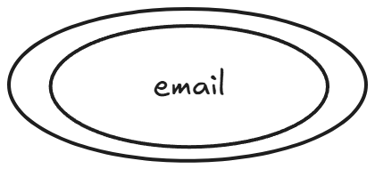
email TEXT NOT NULL UNIQUE,
created_at TIMESTAMPTZ NOT NULL DEFAULT NOW()
);Use migrations or schema versioning tools so the structure evolves safely, and pair them with data validation scripts where sensible.
Optimization and maintenance#
After the build is live, monitor performance and tune accordingly. Introduce indexes when queries slow, and rely on views, stored procedures, or materialized tables to keep common operations efficient. Set up scheduled backups, test restores, and automate health checks so the system remains reliable as workload grows.
Entity-Relationship modeling#
The ER model keeps your conceptual work visual. It draws entities as rectangles, relationships as diamonds or lines, and associates attributes to their owning entity. This technique has endured because pictures reveal cardinality patterns and optional links faster than prose alone.

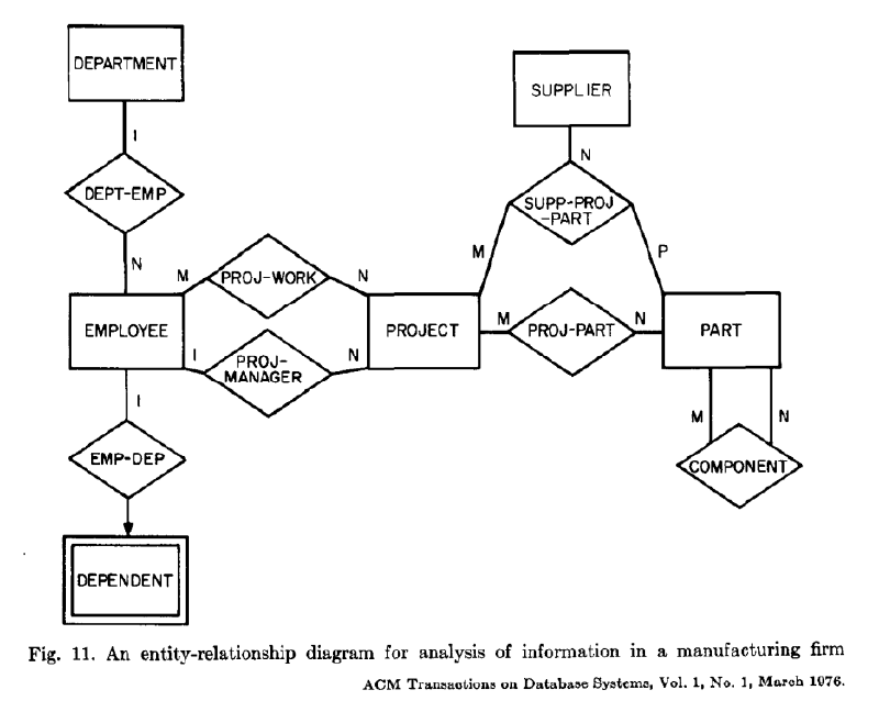
Peter Chen framed this approach in 1976, explaining that the ER model “incorporates important semantic information about the real world,” and that the diagrammatic technique is a tool for design rather than documentation alone.
Entities#
Entities represent things with distinct identities, such as users or products. They have attributes that capture their properties and serve as the source of truth for their lifecycle. Weak entities, like order line items, rely on another entity’s key to be uniquely identified and therefore inherit part of their identity from a stronger parent.

Relationships#
Relationships describe how entities interact. Cardinality (one-to-one, one-to-many, many-to-many) and optionality (mandatory vs optional participation) govern the physical design of junction tables or nullable columns. Explicitly modeling these properties helps reviewers see why a pair of tables needs a foreign key and what the expected multiplicity is.
Associations#
Cardinality tells us how many members of one entity can or must participate in a relationship with another entity. It is not a mere label: it determines whether the relationship can be enforced with simple foreign keys or whether it requires an intersection table. These are the standard patterns:
- 1:1 (one-to-one) - each instance of Entity A corresponds to at most one instance of Entity B, and vice versa; useful when some properties are optional but closely tied.
- 1:n (one-to-many) - one instance of A can own many Bs, but each B refers back to a single A; the foreign key is placed on the “many” side.
- n:m (many-to-many) - both sides allow multiple matches; a join table captures the association and any attributes specific to the relationship.
Every real-world scenario picks one cardinality per relationship based on the business rule, and that choice hints at how constraints map onto tables later. Optionality tells a complementary story: it identifies whether participation in the relationship is mandatory (one and only one) or optional (zero or one). When optionality is undetermined or temporarily irrelevant - for example, when you do not yet know whether every customer will make a second purchase - you can model the relationship with the broader One or Many notation and refine it later, just like the pioneers in The Origins of Databases did to keep schemas flexible.
Optionality and lower bounds#
The difference between One and One (and only one) lies in that lower bound: the former leaves room for zero occurrences, while the latter insists on exactly one. Similarly, Many by itself means “zero or more,” whereas Zero to Many or One to Many spell out the permitted range explicitly. Keeping the lower bound unspecified at first is a deliberate choice when requirements are likely to evolve, but every change request should revisit the optionality because it suddenly affects whether a foreign key column is declared NOT NULL or nullable and whether cascading deletes are appropriate.
When a relationship is optional for one side but mandatory for the other, the side that can be optional is usually the one that stores the foreign key, and the mandatory side is the parent. This asymmetry is what makes ER modeling a conversation about both cardinality and participation, not just about drawing lines between boxes.
Attributes#
Attributes describe the descriptive properties of an entity. An entity such as User may expose attributes like email, full name, birth date, and city. Some attributes are atomic (single-valued), while others are composite, derived from a set of smaller fields - for example, a full name attribute composed of first name and last name. If an attribute can store multiple values (a user with several phone numbers), we denote it as a multivalued attribute and plan how the logical schema will normalize those repetitions.
When translating the conceptual model into tables, we represent only atomic attributes as columns. Composite attributes are peeled apart, and multivalued attributes usually become separate tables unless the values can be stored in a structured column such as an array (which is more typical in NoSQL designs). Understanding attribute categories at this stage keeps the logical model clean and prepares it for the precise constraints we introduce in the next phases.
Logical Modeling#
Logical modeling takes the sanitized ER diagram and maps it to tables, columns, data types, and constraints. Instead of drawing boxes, you now specify how each entity translates into a table, how relationships turn into foreign keys, and which attributes live where. Follow a four-phase approach to keep the work organized and to make sure every relationship gets the appropriate treatment.
Entities become tables#
Every entity becomes a table, and only atomic attributes remain as columns. Choose a primary key for each table (natural keys such as email are acceptable when they are stable).
| User | |
|---|---|
| Pk | |
| name | |
| birth_date | |
| city | |
| postal_code | |
| street |
Weak entities become tables#
Weak entities (those that depend on another entity for identity) also turn into tables, but they inherit the primary key of their parent as a foreign key.
| Loan | |
|---|---|
| Fk | book_id |
| Fk | user_id |
| start_date | |
| duration_days |
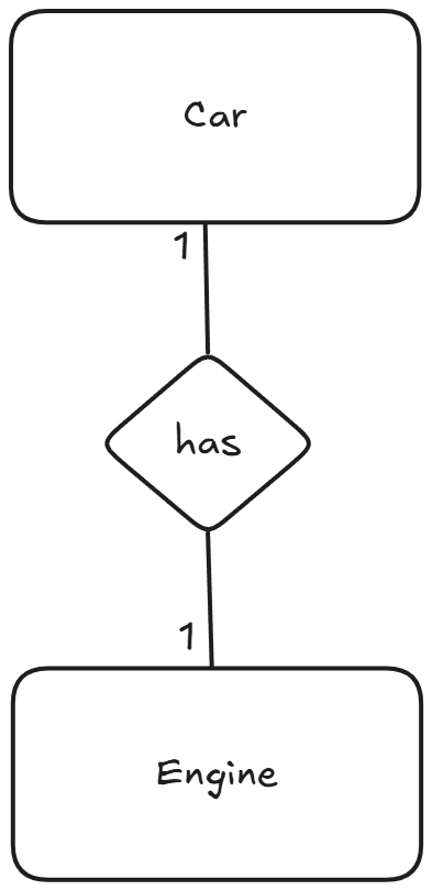
One-to-one relationships#
For one-to-one relationships, copy the primary key from one table to the other and make it a foreign key; any relationship attributes go with the table holding the foreign key.
| Engine | |
|---|---|
| Pk | engine_id |
| Fk | car_id |
| power | |
| type |
| Car | |
|---|---|
| Pk | car_id |
| model | |
| color | |
| year |
One-to-many relationships#
Choose the entity on the “many” side to carry a foreign key pointing to the “one” side, and place any relationship-specific attributes alongside that foreign key.
| Apartment | |
|---|---|
| Pk | apt_id |
| Fk | building_id |
| number | |
| floor |
| Building | |
|---|---|
| Pk | building_id |
| street | |
| year_built |
Many-to-Many Relationships#
When two entities must point to each other multiple times, a direct foreign key creates ambiguity. The remedy is an associative table that carries the foreign keys from both tables plus any attributes that describe the relationship itself. This ensures both participating entities stay normalized and the combined key enforces uniqueness.
- Identify which tables participate in the relationship and decide if the connection truly requires a separate join table.
- Create the associative table (for example,
emp_prj) and move relationship-specific attributes such asroleorassignment_dateinto it. - Declare each participating primary key as a foreign key and use the combination as the associative table’s composite primary key.
| project | |
|---|---|
| Pk | project_id |
| title | |
| start_date | |
| duration_weeks |
| employee | |
|---|---|
| Pk | user_id |
| full_name | |
| emp_prj | |
|---|---|
| Fk | user_id |
| Fk | project_id |
| role |
This structure echoes the relational integrity principles highlighted in The Origins of Databases, where explicit keys avoid implicit assumptions.
Multivalue Attributes#
Lists of values that belong to a single entity, like multiple emails or certifications, belong in their own tables so that each value is a first-class row.
- Create a new table for each multivalue attribute, naming it after the attribute or the entity-attribute pair.
- Add the parent entity’s primary key as a foreign key in the new table, and combine it with the attribute itself when uniqueness is required.
- Keep any metadata about that attribute (for example,
labelorverified_at) within the multivalue table so it stays close to the repeated value.
| Pk | |
| Fk | user_id |
| User | |
|---|---|
| Pk | user_id |
| full_name | |
| date_of_birth |
Now each email row links back to User, and the composite key email + user_id prevents duplicate addresses per user while still allowing the same domain across the wider system.
Key points#
- Cardinality and optionality jointly define how relationships behave and how they later map to keys.
- Using broader labels such as
OneorManycan keep diagrams flexible until requirements settle. - Attributes come in atomic, composite, and multivalued flavors, and logical modeling keeps only the atomic fields as columns.
- Exercises such as the library or the workshop system encourage explicit notation for join tables and mechanic assignments.
- Logical modeling proceeds in phases that translate entities, weak entities, and relationship rules into tables and keys.